| ☰ Menu | The NORUSCA II All-Sky Cameras |
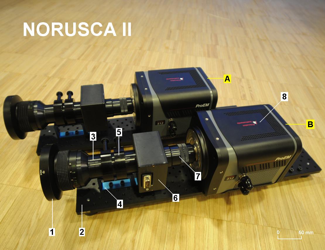
Figure 1. The NORUSCA II 1th Generation all-sky cameras (A) and (B). (1) front element of all-sky lens, (2) mount plate, (3) collimator lens tube, (4) lens mount,
(5) ring holders, (6) filter box, (7) camera lens, and (8) EMCCD detector. Photo and text: F. Sigernes @UNIS February 2011.
Two of a kind ...
The NORUSCA II cameras are named after a research project called: Norwegian and Russian Upper Atmosphere Co-operation on Svalbard part 2, which is founded by the Norwegian Research Council (project #196173). The aim of the project is to install 2 identical state of the art all-sky color camera systems at KHO and the Auroral station in Barentsburg (BAB) operated by the Polar Geophysical Institute (PGI) in Russia. Fig. 1 shows the assembled cameras, ready for tests and calibration.
The instrumental design includes a new high power all-sky lens (f/value = 1.0). The lens is designed and constructed by Dr. Yuriy Ivanov from the Main Astronomical Observatory (MAO) of the National Academy of Sciences (NAS) in Ukraine. The design includes a section or chamber where the light is nearly parallel before it’s focused onto the detector. See label (2) in Fig. 2. Note that there is no telecentric lens system in the design. This reduces the number of active optical elements needed, and as a consequence the throughput is increased. A prototype has been tested by PGI under field conditions in Apatity and in Barentsburg.
The instruments use newly developed state of the art electro-optical wavelength tunable filters from Cambridge Reseach & Instrumentation, Inc. (CRi). The filters are known as Liquid Crystal Tunable Filters (LCTFs) or as VariSpec filters. Spectral tuning is obtained by using liquid crystal variable retarders to a Lyot filter design (uses the effect of double refraction and polarization to separate wavelengths). A series of optical elements are bounded together with index-matching epoxy. Each element transmits light with transparency that varies sinusoidal as a function of wavelength. The transmitted light adds constructively in the desired bandwidth region and destructively everywhere else within the wavelength region of the filter.
The spectral range of the filter covers the visible part of the electromagnetic spectrum from 400 – 720 nm. The bandwidth is 7 nm. The size and the 35 mm aperture of the filter match the lens chamber and the diameter of the parallel light beam perfectly. The filter switches from one wavelength to another in just 50 ms. The transmission factors of the filter are ~ 10, 40 and 45 % at wavelengths 430, 560 and 630 nm, respectively. The filters are more red than blue sensitive. This is compensated by a high blue sensitive EMCCD detector from the company Princeton Instruments.
The assembled system is in other words capable of imaging several wavelengths of the aurora (f. ex. 4278 Ĺ N2+, 5577 Ĺ [OI], 6300 & 6364 Ĺ [OI]) almost simultaneously with no moving parts! Furthermore, with 2 cameras installed at each site (KHO and BAB), we can obtain 3D color information from auroral arcs in near real time.
First sample data
Partners: UNIS, PGI and Keo Scientific Ltd.
The NORUSCA II cameras are named after a research project called: Norwegian and Russian Upper Atmosphere Co-operation on Svalbard part 2, which is founded by the Norwegian Research Council (project #196173). The aim of the project is to install 2 identical state of the art all-sky color camera systems at KHO and the Auroral station in Barentsburg (BAB) operated by the Polar Geophysical Institute (PGI) in Russia. Fig. 1 shows the assembled cameras, ready for tests and calibration.
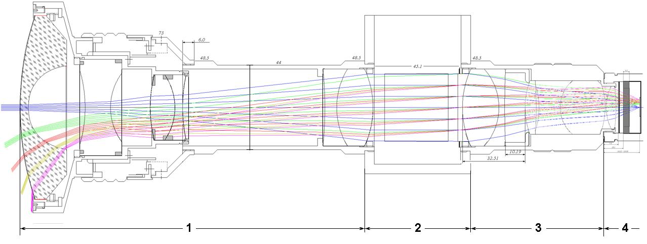
Figure 2. Lens mechanics and optical diageram of the NORUSCA II all-sky lens. (1) focusing mechanism and collimator lenses, (2) filter box / chamber, (3) camera lens, and (4) camera head.
The instrumental design includes a new high power all-sky lens (f/value = 1.0). The lens is designed and constructed by Dr. Yuriy Ivanov from the Main Astronomical Observatory (MAO) of the National Academy of Sciences (NAS) in Ukraine. The design includes a section or chamber where the light is nearly parallel before it’s focused onto the detector. See label (2) in Fig. 2. Note that there is no telecentric lens system in the design. This reduces the number of active optical elements needed, and as a consequence the throughput is increased. A prototype has been tested by PGI under field conditions in Apatity and in Barentsburg.
The instruments use newly developed state of the art electro-optical wavelength tunable filters from Cambridge Reseach & Instrumentation, Inc. (CRi). The filters are known as Liquid Crystal Tunable Filters (LCTFs) or as VariSpec filters. Spectral tuning is obtained by using liquid crystal variable retarders to a Lyot filter design (uses the effect of double refraction and polarization to separate wavelengths). A series of optical elements are bounded together with index-matching epoxy. Each element transmits light with transparency that varies sinusoidal as a function of wavelength. The transmitted light adds constructively in the desired bandwidth region and destructively everywhere else within the wavelength region of the filter.
The spectral range of the filter covers the visible part of the electromagnetic spectrum from 400 – 720 nm. The bandwidth is 7 nm. The size and the 35 mm aperture of the filter match the lens chamber and the diameter of the parallel light beam perfectly. The filter switches from one wavelength to another in just 50 ms. The transmission factors of the filter are ~ 10, 40 and 45 % at wavelengths 430, 560 and 630 nm, respectively. The filters are more red than blue sensitive. This is compensated by a high blue sensitive EMCCD detector from the company Princeton Instruments.
The assembled system is in other words capable of imaging several wavelengths of the aurora (f. ex. 4278 Ĺ N2+, 5577 Ĺ [OI], 6300 & 6364 Ĺ [OI]) almost simultaneously with no moving parts! Furthermore, with 2 cameras installed at each site (KHO and BAB), we can obtain 3D color information from auroral arcs in near real time.
First sample data
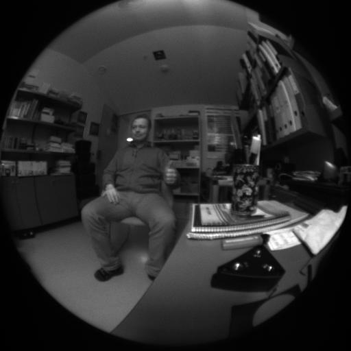
Figure 3. Screen dump of raw data from the camera at 630 nm. View from authors office desk at UNIS.
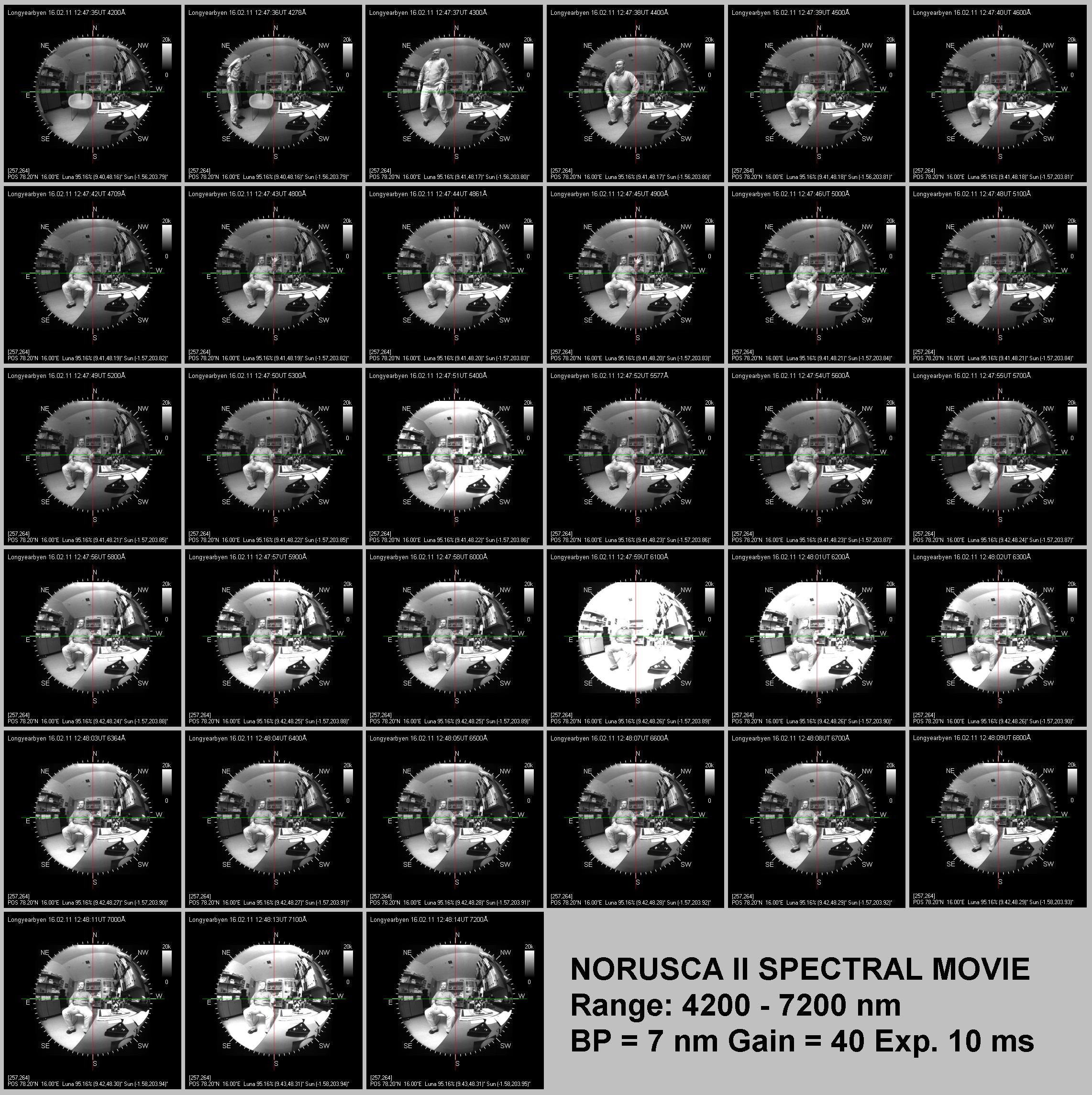
Figure 4. Spectral movie from 420 to 720nm.
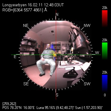
Figure 5. Composite RGB color image. Red (R) 636.4 nm, green (G) 557.7 nm and blue (B) 486.1 nm.
Partners: UNIS, PGI and Keo Scientific Ltd.