| ☰ Menu | Experiment |
1 The University Centre in Svalbard (UNIS), Norway
2 Norwegian University of Science and Technology (NTNU), Trondheim, Norway
3 University of Oslo, Oslo, Norway
In the following tests, the default 50 mm front objective from Edmund Optics (EO) is replaced by several candidates including a Nikon 500 mm reflex lens, a Sky-Watcher 400 mm Apochromatic refractor objective (APO), a 6 inch diameter Celestron Schmidt-Cassegrain (C6) and a 8 inch diameter Celestron Rowe - Ackermann Schmidt Astrograph (RASA 8) telescope.
nm_EO50mm_Xvid_5nm.png)
In order to compare the different candidates, the HSI v6 was first used with the standard 50 mm focal length objective from Edmund Optics. Figure 2 shows a color RGB composite generated from the hyperspectral data cube, using center wavelengths 486, 557 and 630 nm representing blue, green and red color channels, respectively. Spectral resolution was set to 5 nm. An exposure time of e = 33 msec is used, which corresponds to 30 Frames Per Second (FPS). Note that the image is downsized vertically 50% and color auto balanced by Paint.net. The above is the standard procedure followed for images generated in this test.
The instrument was mounted on a rotary tablet (Syrp Genie Mini II) to sweep ΔΦ = 30° horizontally in P = 60s. The scenario is looking through an office window at UNIS towards North-East in Longyearbyen.
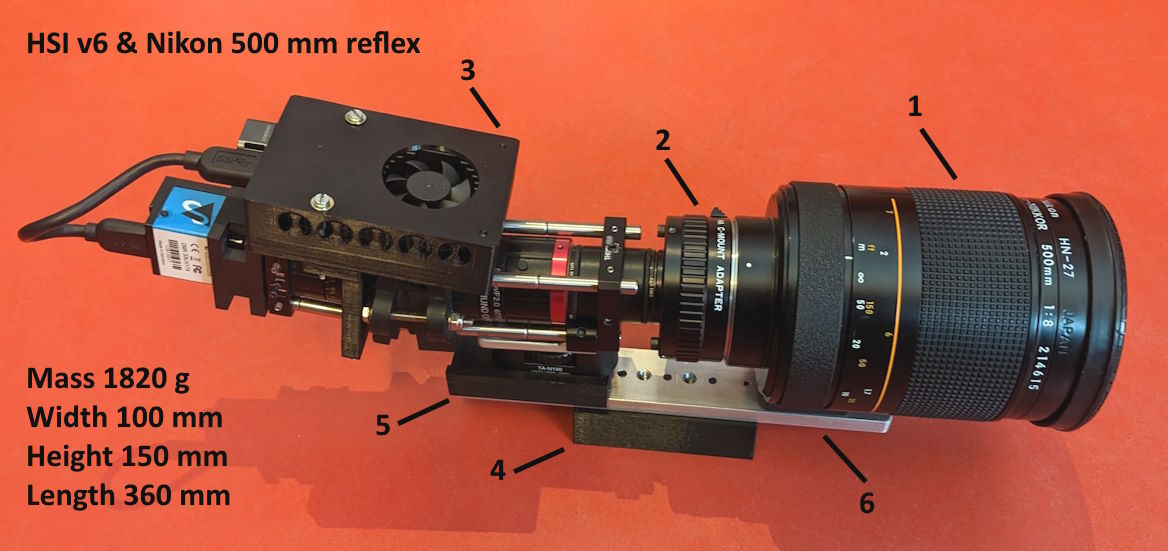
The Nikon 500 mm reflex telephoto lens was mounted to the HSI v6 as shown in Figure 3. The size and mass of the lens required extra mount support by an aluminum bar and a 3D printed spacer. The diameter of the lens is close to 90 mm and its about 140 mm long. The mass is 815 g. In addition, a 3D printed dovetail was made to fit the Vixen style saddle of the iOptron MiniTower II motorized telescope Goto mount.
nm_Nikon500mm0008X_5nm.png)
The Goto mount was set to sweep ΔΦ = 2° in azimuth for a period (P) of about one minute. This is speed setting 8X for the motors. Angular speed is then only ω = 0.035°/s. The resulting color composite is shown in Figure 4. The distance to the target is approximately 250 meters. See target area marked with red box in Figure 2.
The F/8 aperture of the lens required a gain setting at 29.8 dB in order get a reasonable 8-bit signal count. Range is 0 - 48 dB. The image quality seems to be improved especially in the deep blue and red parts of the spectrograms. They simply look sharper than before. This behavior is expected due to the fact that the instrument is now illuminated more in the center of the lenses at F/8 compared to F/2.8. On the other hand, it was hard to focus the lens. The focus ring was very sensitive to movement / rotation.
Note that the Raspberry PI 4 is an optional mobile recording unit for the instrument. An USB3 cable may also be used directly connected to a laptop computer running Windows 11. The PI runs on the Raspbian OS with Python drivers and OpenCV. Remote control is obtained by configuring the PI as a wireless Wi-Fi hotspot and enabling the built in VNC server. Power is then supplied by a mobile phone 12Ah power bank. With this configuration the PI can operate approximately 4 hours assuming a power consumption of maximum 3A.
nm_Nikon500mm2X0002x_5nm.png)
The focus was extremely challenging and the whole system was very sensitive to vibrations during scanning. See edge of solar panels in Figure 5. The extenders are known [5] to reduce image quality based on the fact that they act as a magnifying glass with increased chromatics aberrations, decrease in sharpness and contrast.
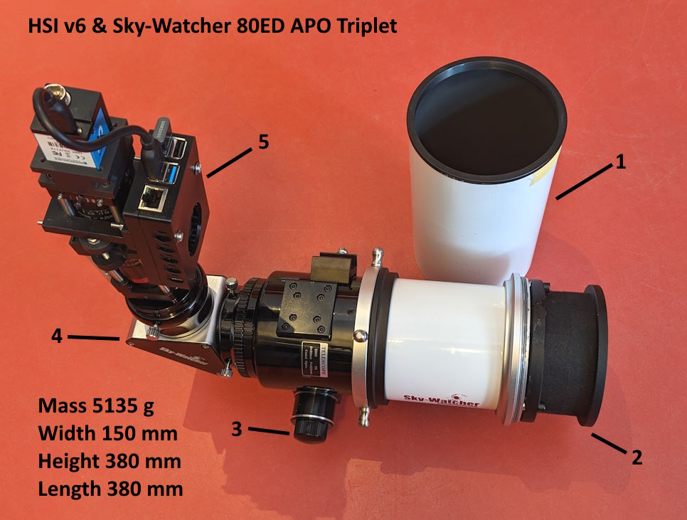
The HSI v6 connects to the APO with a C-mount to 1.25-inch adapter tube directly to the 90° mirror diagonal in the back. All parts are screw tighten by hand, which makes the assembly unstable. This should be addressed if it becomes a candidate for space. The mass is now as high as 5.1 kg and the system length with the Sun shade on becomes 520 mm.
nm_ED800005x_5nm.png)
The aperture of the APO is as low as F/5 with a lens diameter of 80 mm and a focal length of 400 mm. This is the highest light throughput candidate tested so far except from the EO 50 mm at F/2.8. Figure 7 shows the result. Again, it was hard to focus the spectrograms even with the fine adjustment focus knob option of the APO.
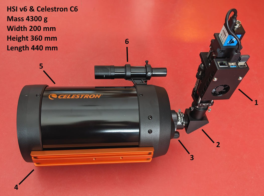
As with the APO, the HSI v6 is connected by a 1.25-inch tube adapter directly to the 90° diagonal mirror in the back of the C6 telescope. The configuration is unstable and should be re-enforced mechanically. The diagonal is made of plastic and should be replaced by metal. A complete disassembly of the telescope must be done do identify other parts that would not survive space.
It is suspected that the focus mechanism inside the tube is not rigid enough to resist vibrations and shocks during launch. The primary mirror slides on the center baffle tube to focus. Reports of primary mirror flops that causes image shifts, occur even using the telescope on a stationary Goto mount.
Figure 9 shows the test image obtained with the MiniTower II set to pan horizontally ΔΦ = 1.52° in P = 3 minutes. This corresponds to speed setting 2X for the motors. Angular speed then becomes ω = 0.0084°/s.
nm_C60003x_5nm.png)
The focus knob has a rubber cover and is very sensitive to focus adjustments. The above test image is not resized, only color balanced by Paint.net. The slow sweep period of P = 180s with 5417 recorded spectrograms resulted in close to square image pixels with no vertical binning necessary.
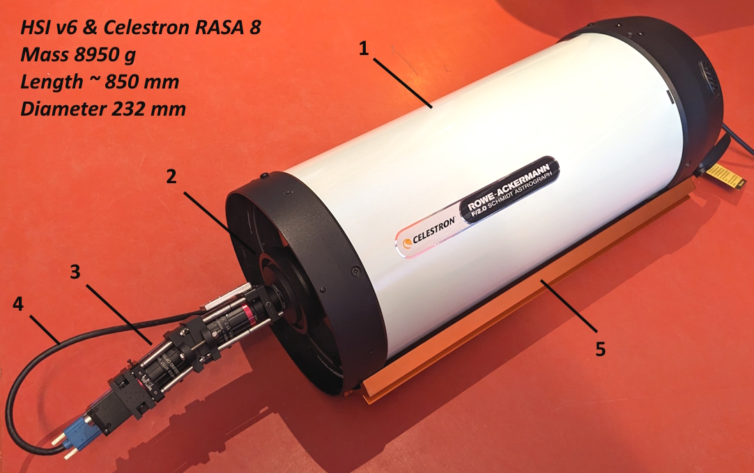
The HSI v6 connects to the RASA 8 telescope objective by a C-mount adapter. This setup requires the HSI v6 to be mounted within the central obstruction diameter of 93 mm. The 200 mm spectrograph length is no limitation since it is not obscuring the field of view on the sides. Note that the telescope also needs to be stopped down to F/2.8 to match the HSI v6 collimator lens. In this experiment, the RASA 8 is the fastest alternative due to its high aperture at F/2 and high throughput.
nm_C80013x_5nm.png)
The RASA 8 telescope was the hardest to focus due to the high aperture and that it is most probably overfilling the field of view of the collimator lens of the spectrograph, which will introduce stray light. A study should be conducted to reduce the telescope aperture to match the spectrograph. Whether this could be achieved by either blocking the entrance aperture of the Smith corrector or reducing the F/number of the 4-element lens group facing the main mirror, remains to be decided.
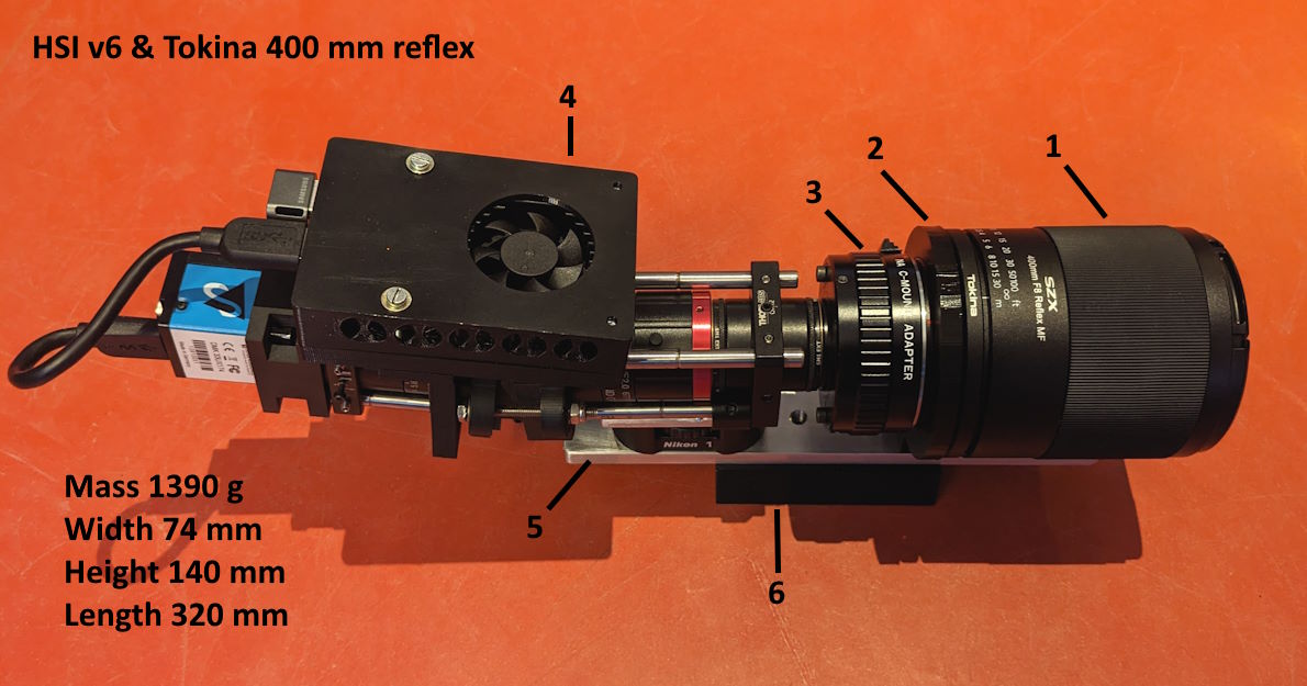
The Tokina 400 mm reflex lens is mounted the same way as the Nikon 500 mm reflex lens. As shown in the above image, a 3D printed ring mount is made to fix the lens to the supporting aluminum bar with the telescope dovetail and the HSI v6. The instrument is the most compact sized, lightweight (mass = 1.4 kg) and low-cost (less than 400 USD) telescope design used in this experiment.
The Tokina lens is made of metal except for the lens caps. It should be disassembled to identify other non-surviving out in space parts. An option is to use the included 2X lens extender to increase the focal length to 800 mm at the cost of reducing the aperture to F/16. The extender will increase the system length by 36 mm and the mass by 116 g. Note that the Tokina objectives are part of a new production line of reflex lenses with several other focal length options (2022).
nm_Tokina0005_Xvid_5nm.png)
As with its Nikon relative, focused is achieved by moving the secondary mirror instead of the primary one using a fine threaded outer tube.
The above image test shows similar performance as the Nikon lens. The sun was at a low elevation of 6° above the horizon, blocked by the surrounding mountains of Longyearbyen. The light conditions became relatively low compared to the Nikon test where the sun elevation was 23°. The effect is seen in the two windows to the right where the Indoor gas discharge tube lights shine. As a result, the gain was pushed to a maximum of 48 dB to obtain a usable 8-bit signal.
Figure 14 shows the spectrogram frames that crosses through the center of the red logo of the company Hurtigruten AS for each telescope candidate. The Fraunhofer lines are seen as vertical dark stripes in all the frames. The O2 atmospheric absorption line is clearly detected at wavelength 759.37 nm. It is possible to use these lines for in-orbit characterization of instrumental performance such as wavelength calibration, spectral bandpass, smile effects, keystone, and in-correct optical alignment [3] caused by shock or vibration effects during launch.
In the spatial domain, horizontal features or edges should be as sharp as possible to obtain focus. Any change in shape across the spectrum, indicates chromatic abbreviations or in-correct illumination such as overfilling the field of view of the collimator lens.
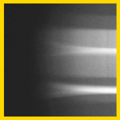
Fig. 15. Zoomed version of rectangle in panel (E) of Figure 14.
|
The effect is noticeable in the yellow rectangle in panel (E) for the deep blue part of the spectrum.
The RASA 8 telescope was hard to focus with feature deformation at the edges of the spectrogram.
Here lines and edges became bended, wider, and focus was lost.
Note that this will propagate into the Near-Infra Red (NIR) part as a second order blurry background contribution to the spectrogram.
|
Furthermore, the use of the 2X lens extender on the Nikon 500 mm reflex lens in panel (B) is suspected to show similar effects with increased chromatic aberration and loss of sharpness and contrast [5]. However, together with the Celestron C6, it gave the most detailed results in this test due to the high magnification. In both cases, it is possible to read the top text: Hurtigruten. But as seen in panels (B) and (D), the edges are not razor sharp. The spectrogram from Sky-Watcher APO Triplet in panel (C) shows straight edges and lines across the spectrum, which indicate low chromatic abbreviation. But again, edges are not in sharp focus.
The most surprising results are from the SLR (Single-Lens reflex) catadioptric lenses in panels (A) and (F). Both the Nikon 500 mm and the Tokina 400 mm reflex objectives were a challenge to focus, but the process was less time-consuming compared to focusing the Celestron telescopes and the Sky-Watcher APO. Lines and edges are acceptable sharp with no change in shape across the spectrum. In addition, the compactness and low mass make them the suitable candidates for small satellites.
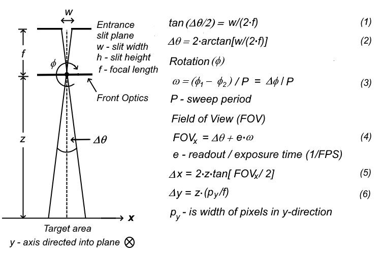
The above shows how to estimate the spatial resolution assuming no movement other than rotation between target and instrument. Calculated values are given in the tables below as a function of frame rate (FPS) and font optics.
The angular speed for the iOptron MiniTower II is ω = 0.035°/s. The Syrp Genie tablet is set to ω = 0.5°/s. The latter is only used for the EO-50 lens. The entrance slit is 0.05 x 7 mm2 in size. The Sony IMX174 CMOS has 1920 x 1080 pixels. The size of the pixels is 5.86 µm square. D is outer diameter of font optics. Also known as the Optical Tube Assembly (OTA) front diameter.
| Target distance z (FPS=30) | |||||||
| Front Optics | |||||||
| EO-50 | |||||||
| Sky-Watcher 80ED | |||||||
| Celestron RASA 8 | |||||||
| Tokina Reflex | |||||||
| Nikon Reflex | |||||||
| Nikon Reflex 2X | |||||||
| Celestron C6 | |||||||
Table 1. Spatial resolution numbers with FPS = 30 frames per second.
| Target distance z (FPS=20) | |||||||
| Front Optics | |||||||
| EO-50 | |||||||
| Sky-Watcher 80ED | |||||||
| Celestron RASA 8 | |||||||
| Tokina Reflex | |||||||
| Nikon Reflex | |||||||
| Nikon Reflex 2X | |||||||
| Celestron C6 | |||||||
Table 2. Spatial resolution numbers with FPS = 20 frames per second.
| Target distance z (FPS=10) | |||||||
| Front Optics | |||||||
| EO-50 | |||||||
| Sky-Watcher 80ED | |||||||
| Celestron RASA 8 | |||||||
| Tokina Reflex | |||||||
| Nikon Reflex | |||||||
| Nikon Reflex 2X | |||||||
| Celestron C6 | |||||||
Table 3. Spatial resolution numbers with FPS = 10 frames per second.
Table 1-3 list the spatial resolution as a function of target distance for all candidates in this test. Note that the resolution along track (Δx) is larger than resolution across (Δy). The latter is because the Δx depends on rotation along track and the rather large slit with w = 50 µm compared to the size of one single pixel py = 5.86 µm.
| Sony CMOS 1-4th generation pixel size py [µm] | |||||||
| Front Optics | |||||||
| EO-50 | |||||||
| Sky-Watcher 80ED | |||||||
| Celestron RASA 8 | |||||||
| Tokina Reflex | |||||||
| Nikon Reflex | |||||||
| Nikon Reflex 2X | |||||||
| Celestron C6 | |||||||
Table 4. Spatial resolution numbers with FPS = 30 frames per second. Target distance is 540 km. Δx and Δy units are in meters [m]. Pixel sizes correspond to Sony 1-4th generation CMOS sensors.
Additional information and basic theory of operation of hyperspectral pushbroom imagers are listed in [6]. Furthermore, the attitude control system of the HYPSO satellites allows the possibility to perform agile spacecraft maneuvers that will improve both the Signal-to-Noise Ratio (SNR) and spatial resolution. One example is to successively pushbroom record during a single pass a target scene along and across of the satellite ground track [7]. The spatial resolution should then be improved by combining both scenes, utilizing the fact that Δy < Δx for each scan.
Furthermore, The Sony IMX174 is the 1th generation Pregius CMOS sensor (2013). Today there are 4 generations of Sony Pregius CMOS sensors. The trend is smaller pixel size, lower read noise and back illuminated pixels. All with almost no loss of Quantum Efficiency (QE) [8-9]. Table 4 list a factor of approximately 2 times improved across track (Δy) resolution moving from 1th to 4th generation.
| SiOnyx Black Silicon CMOS sensor pixel size py [µm] | ||||
| Front Optics | ||||
| EO-50 | ||||
| Sky-Watcher 80ED | ||||
| Celestron RASA 8 | ||||
| Tokina Reflex | ||||
| Nikon Reflex | ||||
| Nikon Reflex 2X | ||||
| Celestron C6 | ||||
Table 5. Spatial resolution numbers with FPS = 90 frames per second for the SiOnyx Black Silicon CMOS sensor. Target distance is 540 km.
Another sensor option is to use the SiOnyx Black Silicon CMOS sensor. It is found to be 3 times faster than the Sony IMX174. It operates at default 90 FPS with increased sensitivity [10], especially in the NIR region of the spectrum. The size of the of the sensor (12.3 x 9.9 mm2) is larger compared to the IMX174 (11.3 x 7.1 mm2). This enables us to use a 10 mm instead of 7 mm long slit. The square pixel size has also increased from 5.86 to 9.5 µm. Table 5 lists spatial resolution in nominal mode.We propose that a study should be conducted to choose the optimal sensor candidate.
- M. E. Grøtte, R. Birkeland, E. Honore-Livermore, S. Bakken, J. L. Garrett, E. F. Prentice, F. Sigernes, M. Orlandic, J. T. Gravdahl, T. A. Johansen, Ocean Color Hyperspectral Remote Sensing with High Resolution and Low Latency - the HYPSO-1 CubeSat Mission, IEEE Trans. Geoscience and Remote Sensing, Vol. 60, pp. 1-19 (2022), https://doi.org/10.1109/TGRS.2021.3080175
- M. Henriksen, E. Prentice, C. van Hazendonk, F. Sigernes, and T. Johansen, Do-it-yourself VIS/NIR pushbroom hyperspectral imager with C-mount optics, Opt. Continuum 1, 427-441 (2022), https://doi.org/10.1364/OPTCON.450693
- S. Bakken, M. B. Henriksen, R. Birkeland, D. D. Langer, A. E. Oudijk, S. Berg, Y. Pursley, J. L Garrett, F. Gran-Jansen, E. Honore- Livermore, M. E. Grøtte, B. A. Kristiansen, M. Orlandic, P. Gader, A. J. Sørensen, F. Sigernes, G. Johnsen and T. A. Johansen, HYPSO-1 CubeSat: First Images and In-Orbit Characterization, Remote sensing, 15(3), 755 (2023), https://www.mdpi.com/2072-4292/15/3/755
- Fred Sigernes, Marie Bøe Henriksen, Sivert Bakken, Joseph Garrett, Eirik Selnæs Sivertsen, Roger Birkeland, Mariusz Eivind Grøtte and Tor Arne Johansen, Proposal drafts: [I] and [II] HYPSO-3 Hyper Spectral prototypes, Norwegian Space Agency, January 25, 2023.
- Dan Carr, Shutter Muse, January 5, 2020, Tutorial: The Ultimate Guide To Extenders Or Teleconverters, https://shuttermuse.com/ultimate-guide-to-extenders-teleconverters/
- Hyper spectral Imaging, [pdf], F. Sigernes, AGF-331: Remote Sensing and Spectroscopy - lecture notes, University Centre in Svalbard (UNIS), 2000 - 2007.
- Dennis D. Langer, Joseph L. Garrett, Bjørn A. Kristiansen, Sivert Bakken, Simen Berg, Roger Birkeland, Tommy Gravdahl, Tor A. Johansen and Asgeir J. Sørensen, Agile Maneuvers for Push-Broom Imaging Satellites, IEEE Trans. Geoscience and Remote Sensing, 63 (2024), https://doi.org/10.1109/TGRS.2024.3517696
- Lucid Vision Labs, Tech brief, Sony 4th Generation Pregius S - The Next Evolution of Image Sensors?, https://thinklucid.com/tech-briefs/sony-4th-generation-pregius-s/
- Basler AG, Learning HUB Vision Campus, Sony Pregius S: Advanced sensor technology, https://www.baslerweb.com/en/learning/sony-pregius-s-sensors/
- Fred Sigernes, Roger Birkeland, Joseph Landon Garrett, Henrik Øvrebø, Håvard Brovold, Sivert Bakken, Gaspar Mougin-Trichon, and Tor Arne Johansen, Near infra-red black silicon pushbroom hyperspectral imager, Opt. Continuum 4, 454-465 (2025), https://doi.org/10.1364/OPTCON.549308